Signal to Noise Ratio (SNR) is a figure of merit that compares the level of a desired signal to the level of background noise. It is calculated as the ratio of signal power to the noise power. SNR is expressed in dB (decibles).
For loud signals you can roughly calculate SNR off the S-meter. If a received CW signal is S9 and the meter reads S7 without a signal, the SNR is 12dB (normally each S-unit is 6dB). Let's say this signal is received through a wide receiver filter bandwidth of 2400 Hz. Now apply the narrow 500 Hz CW filter. The noise reading should go down to just under S6 for a 6.8dB improvement. This is the ratio of the two bandwidths. The narrow bandwidth filters out more noise so your SNR improves. The SNR is now 18.8 dB. Note however that the signal of interest must still fully pass through the filter. Passing an SSB signal that is nominally 2300Hz wide through a 500 Hz filter would make the signal unintelligible.
Noise is throughout the radio frequency spectrum. It can be dominated by external noise received by the antenna (the usual case for RF signals < 30MHz, HF) or by the internal noise added by the receiving system (the usual case for signals >30MHz, VHF, UHF).
From Figure 1 you can see that noise is a broadband signal and to measure its power we must specify the bandwidth it is measured in, known as the Noise Bandwidth (NBW).
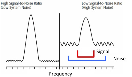
Figure 1: Comparison of different SNRs. Signal power (red) is compared to noise power in a received bandwidth (blue)
SSB signals are normally received through either a 2600 Hz or 2400 Hz filter. Across the amateur radio community 2500 Hz has been adopted as a figure of merit for comparing the receiving capability of a mode. By mode I am referring to SSB, CW, RTTY, JT65, etc. There are pros and cons to the use of each mode. For instance SSB is a signal that is 2300 Hz wide. If you put in smaller filters you start to loose signal energy in addition to lowering the noise energy. This loss of signal will quickly make the SSB signal unintelligible. Bandwidth becomes the limiting factor for the SSB mode.
CW is a much narrower signal. Common filters used include 2400Hz, 500Hz, 250Hz, and 100Hz. With DSP (Digital Signal Processing) you can even go narrower.
Essentially this is what all of the new DSP modulation schemes are doing. They are doing DSP to narrow the noise bandwidth as tight to the signal as possible. In addition to this they are also encoding the signal. Encoding means they are putting in redundant information and/or reducing the alphabet, or known outcomes*1, of the decoded signal. Encoding improves the data recovery of a signal at a given SNR. The scope of encoding the signal is beyond this discussion.
Concentrating on HF amateur communications a DXer is focused on long distance, usually weak, signals. Different modulation modes inherently have different performance on weak signals. Let's look at some common modes used for DXing. It is common in the amateur radio literature to express SNR performance, ie the ability to hear and decode weak signals, in dB releative to noise in a 2500 Hz bandwidth. This is what we show in Figure 2.
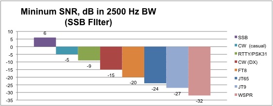
Figure 2: SNR performance referenced to casual copy SSB signal in 2500 Hz
As shown in Figure 2 a 6dB SNR is required for casual SSB communications. A just barely understandable SSB signal (recoginize your call and pull in a signal report) would be 0 db SNR. Note that when we do these SNR comparisons it is on a clear channel. No QRM, no static crashes, no fading. To compensate for these channel characteristics we would need a higher SNR.
Looking at Figure 2 we see for casual CW operation the signal can be 11 dB lower or -5 dB SNR for the same intelligibility as casual SSB. But what does -5 db mean? Doesn't that mean the signal is below the noise? How can you hear that! Remember this is relative to a 2500 Hz bandwidth. You would normally click in a 500 Hz filter and now the -5dB becomes 1.8dB. That's good enough to copy CW. Still too noisy for you? click in the 250 Hz filter and now you have SNR=4.8dB.
In Figure 3 we have recalculated the data in reference to a 100Hz filter. That CW signal that had -5 db SNR in 2500 Hz now has an SNR of 9dB. For A DXer with good ears who is trying to confirm their call and signal report they can go down to -1dB SNR (the brain does some of it's own DSP on the signal). Also, when you are only looking for you call and a signal report to come back, you are in effect reducing the alphabet - and gaining some decoding benefit. For a discussion of what CW SNRs are copyable, see the The Weak-Signal Capability of the Human Ear by Ray Soifer, W2RS.
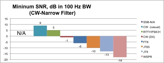
Figure 3: SNR performance referenced to minimal copy CW signal in 100 Hz
For better SNR performance you need to use one of the DSP modes. JT651 was initially developed for EME communications where the signal is very weak. JT65A has been adapted for HF use as JT65-HF2. From Figure 2 you can see that if your JT65A SNR is reported as -15 or lower you are receiving a signal that is too weak for conventional CW reception. Using JT65 you can increase your reception of signals by 9 db (24-15). When using this mode note that it will never report a signal greater than -1dB. The software caps the reporting of strong signals at this level. This goes back to what JT65 was originally designed for: EME. The DSP code as written does not know what to do with a positive SNR signal3. In my experience anything reported as -10 or larger is a suspect SNR.
WSPR4 is not a two-way communications mode, but a Beacon mode. Narrow DSP filtering and coding increases low signal reception by another 8 db.
JT9 was developed after JT655. It is similiar to JT65 but is much narrower and boasts better performance. Unlike JT65 it was specifically designed for HF operation. It will report positive SNRs.
FT8 was recently developed to mitigate fading during Sporadic-E communications on 6 meters, however it has seen widespread acceptance by the Ham Radio community across the HF and VHF spectrum.
NOTES:
*1Think about when you learned Morse Code. You probably first learned the letters, then the numbers. When you took letters only testing it was easier, the alphabet was reduced without the numbers. You didn't have to worry about confusing B with a 6.
REFERENCES:
1 EME with JT65
2 JT65-HF
3 JT65A max SNR -1dB
4 WSPR
5 JT9
ACRONYMS
SSB=Single Sideband, A narrowband voice communications mode
CW=Continuous Wave, a Morse Code communications mode
HF=High Frequency Radio Spectrum, 3 to 30 MHz
VHF=Very High Frequency Radio Spectrum, 30 to 300 MHz
UHF=Ultra High Frequency Radio Spectrum, 300MHz to 3 GHz
RTTY=Radio Teletype communications mode